On this page
Protocol decode view
The protocol decode view turns the traffic of a connection into a table of frames: one row per request, response or broken fragment, with the checksum checked, requests paired with their responses and every field explained. It reads Modbus RTU, Modbus ASCII and Modbus TCP as it comes, and a private binary protocol once you describe it in a frame template. (Free limits how many frames it decodes and which templates; see the end of this page.)
Each connection has its own panel, under its receive view. To open it:
- View → Protocol Decode Panel shows or hides the focused connection's panel;
- or right-click the receive view and check Protocol Decode.
Then choose a Decoder at the top left of the panel. The receive view is not changed in any way: the decoder reads the same bytes beside it. Both directions are decoded, what the connection sends (TX) and what it receives (RX), each as a stream of its own, so your requests and the device's replies never corrupt each other's frames. On a TCP server or UDP connection every client is decoded apart, and a Peer column appears.
The panel starts hidden and decodes nothing while hidden: bytes that arrive while it is closed are not decoded later, so open it before the traffic you want to look at. The bytes of a file transfer are never decoded. The decoder and whether the panel is shown are saved with each connection in the project.
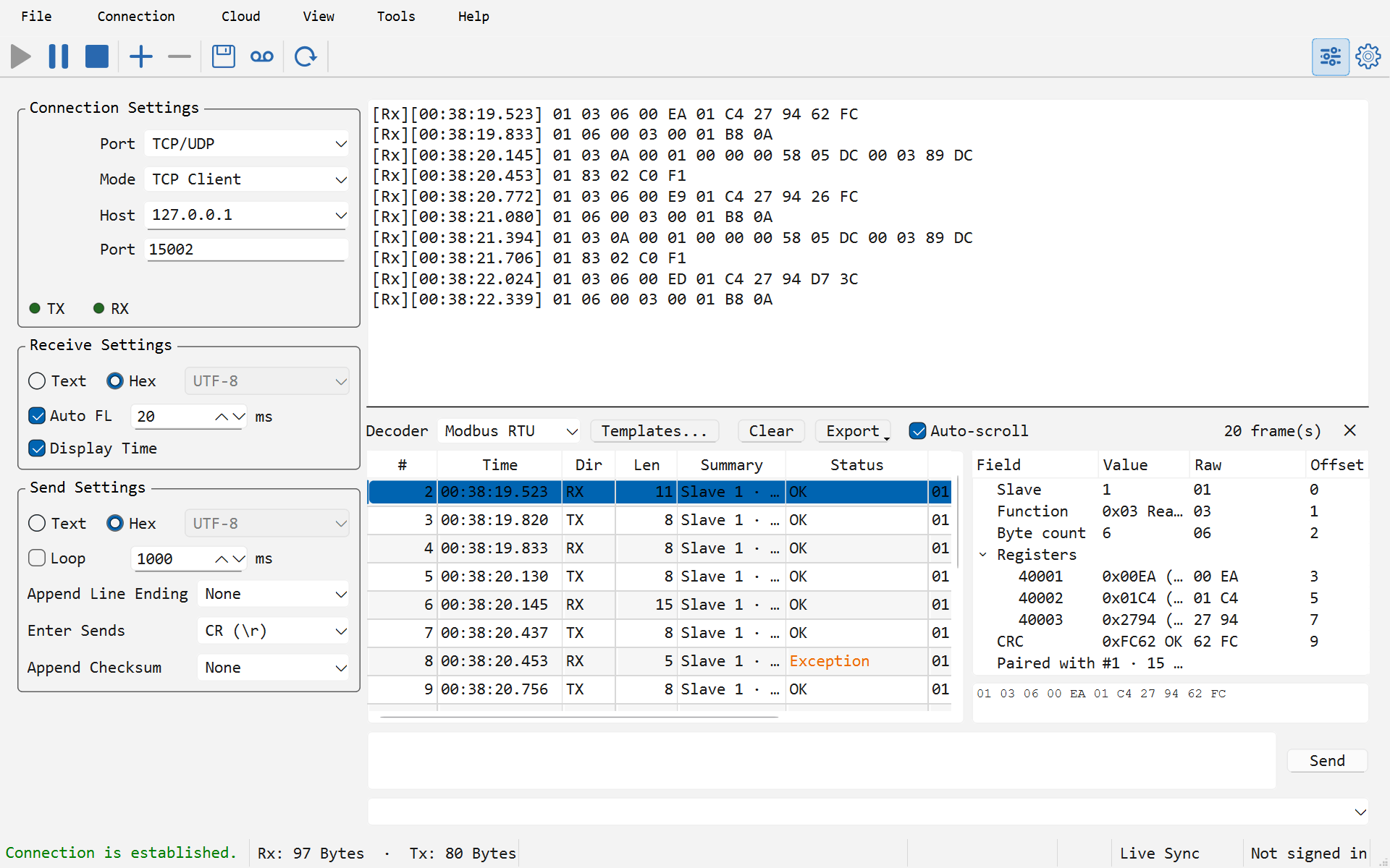
Reading the panel
The row along the top has the Decoder list, Templates... (the frame template editor), Clear (empties the frame table), Export and Auto-scroll; on the right, the number of frames in the table, and ✕ to hide the panel.
The frame table has one row per frame:
| Column | Shows |
|---|---|
| # | The frame's number; it keeps counting when the table is cleared or the decoder changed |
| Time | When the read holding its first byte arrived, to the millisecond |
| Dir | TX or RX |
| Peer | The client's address, on a TCP server or UDP connection only |
| Len | Bytes in the frame |
| Summary | One line: for Modbus the slave, function and range; for a template its first fields |
| Status | See below |
| Raw | The first bytes; the whole frame is in the tool tip and in the hex strip |
| Status | Meaning |
|---|---|
| OK | Complete, checksum good |
| Exception (orange) | A Modbus exception response, checksum good |
| Checksum error (red) | The shape of a frame, but its CRC, LRC or checksum is wrong |
| Malformed (red) | Checksum good or absent, but the shape is wrong: a length that does not match, a bad trailer |
| Incomplete (red) | The line went quiet, or the port closed, in the middle of a frame |
| Unrecognized (grey) | Bytes that belong to no frame; up to 256 bytes per row |
Select a row to see its fields on the right (below the table when the connection is narrow), in four columns: Field, Value, Raw and Offset in the frame. A field in error is shown in red. Select a field and its bytes are highlighted in the hex strip underneath, which holds the whole frame.
When a response is paired with its request, selecting either one tints the other in the table, a Paired with line gives its number and the round-trip time in milliseconds, and a double click on the row goes to it. Right-click a row for:
- Go to Paired Frame;
- Find Bytes in Receive View: jumps to the last place the frame's bytes appear in the receive view. It needs the receive view in Hex, and a frame broken by a timestamp line is not found;
- Copy Hex: the frame's bytes;
- Copy Selected Rows (Ctrl+C).
The table keeps the most recent 5000 frames; the count on the right says how many older ones were dropped. Choosing another decoder, or editing the template in use, empties the table, so every row in it was cut by the decoder you see; renaming a template does not. Connection → Clear All Displays empties the frame tables together with the receive views.
Modbus RTU, ASCII and TCP
Choose the decoder by what is on the wire, not by the kind of connection:
| Decoder | For |
|---|---|
| Modbus RTU | Binary frames ending in a CRC-16, on RS-485 or RS-232, and RTU over TCP through a serial device server |
| Modbus ASCII | Frames written as hex text, starting with : and ending with CR LF, checked by an LRC |
| Modbus TCP | The MBAP header (transaction, protocol, length, unit), usually on port 502, with no CRC |
A TCP connection to a serial device server in "RTU over TCP" mode carries RTU frames, so it takes Modbus RTU. A table that fills up with Unrecognized rows usually means the wrong decoder.
Function codes 01 to 06, 07, 08, 0B, 0C, 0F, 10, 11, 16, 17 and 2B are named and explained field by field: start address and quantity, byte count (checked against the request), coils as ON / OFF, and each register as hex and decimal, with the signed value too when the top bit is set, as in 0xFFFF (65535 / -1). An exception response shows its code and name, for example Slave 1 · Exception 02 Illegal Data Address (Read Holding Registers).
Whether a frame is a request or a response is decided by its shape. Where both fit, as with the echo of a Write Single Register, a matching request still waiting for its answer makes it the response. Direction plays no part, so the decoder works whether SPU is the master, a simulated slave, or only listening on an RS-485 bus where both sides arrive on RX.
A response is paired with the oldest request still waiting that has the same slave and function code (in Modbus TCP, the same transaction ID), from the same client, sent no more than 2 seconds before, which is how a half-duplex bus answers. Slave 0 on a serial line is a broadcast, which nobody answers, so it is never paired.
Register references and PDU addresses
Inside a frame, addresses count from 0: the first holding register is 00 00. Device manuals mostly number them the traditional way instead, from 1 and with a leading digit for the table:
| Reference | Table | Function codes |
|---|---|---|
| 0xxxx | Coils | 01, 05, 0F |
| 1xxxx | Discrete inputs | 02 |
| 3xxxx | Input registers | 04 |
| 4xxxx | Holding registers | 03, 06, 10, 16, 17 |
So "40001" is holding register address 0, and "40108" is address 107, 00 6B on the wire. Above 9999 the six-digit form is used: address 9999 is 410000.
The decoder shows both, so nobody has to do the off-by-one in their head. A start address reads 0x006B = 107 (40108), a request's summary reads 40108-40110 (3), and each register of a paired response is a row named by its reference: 40108, 40109, 40110. When a response's registers are named [0], [1]... instead, its request was not seen: the panel was opened after it went out, or the answer came more than 2 seconds later.
When a device ignores a request or answers with Illegal Data Address, compare the start address against the manual in both forms first: a manual that says "register 1" may mean 40001, which is address 0, or address 1. To check the CRC of a frame you built by hand, see CRC and Modbus checks.
Why RTU frames survive split reads
On paper, a Modbus RTU frame ends with 3.5 character times of silence. That silence does not survive the trip to your computer: a USB serial adapter hands the bytes over in blocks on its own timer, a serial device server packs them into TCP segments on its own, and the operating system merges or splits reads as it pleases. One frame can arrive in two reads, and a fast poll often lands a request and its response in one.
So SPU does not frame RTU by timing. It frames it by the CRC: at the head of the stream it tries the lengths the function code allows, and a length whose CRC checks out makes a frame. When none does, it looks ahead for the next place that could start a frame (slave 0 to 247, a known function code, a length that fits) and whose CRC checks out, and carries on from there; the bytes skipped become an Unrecognized row. Silence only matters for what could not be framed: a frame still incomplete after 100 ms of quiet is shown as Incomplete.
The result is the same frames whether the bytes came through a USB adapter, an RS-485 converter or RTU over TCP. Modbus ASCII is framed by its : and CR LF, and Modbus TCP by the length in its header, so neither depends on timing either.
Frame templates for your own protocol
A frame template describes a private binary protocol: how to find a frame in the stream, how it is checked, and what its fields mean. Open the editor with Tools → Frame Templates... or the panel's Templates... button. Templates are listed on the left, with buttons to add, duplicate, remove and move them up or down; each needs a name of its own. Once saved with OK, every template appears in the panel's Decoder list.
Framing, the Mode that cuts frames out of the stream:
| Mode | A frame is |
|---|---|
| Header + length | The Header (hex) bytes, then a length field somewhere after them: Length at byte N, width 1, 2 or 4 bytes, in a byte order, counts the whole frame, the bytes after it or the bytes after it, up to the checksum, with an adjust of −64 to 64 for protocols that count one more or one less |
| Header + fixed length | The header, then always the same Frame length |
| Delimiter | Everything up to the Delimiter (hex), such as 0D 0A |
| Idle gap | Everything up to a silence of so many ms |
Prefer the two header modes: like RTU above, they do not depend on timing, and a frame that fails its checksum is not given up on at once — when a later header inside it starts a frame that checks out, the search carries on from there. An idle gap is only as reliable as the adapter between you and the device. A Trailer (hex) is optional and checked when set. Largest frame caps a frame at 4 to 4096 bytes, and Frame timeout is how long a half frame waits before it is shown as Incomplete.
Checksum: None, SUM8, XOR8, SUM16, or any algorithm of the CRC calculator, CRC-16/MODBUS included, plus Custom CRC with its width, polynomial, initial value, XorOut and reflection. It covers the bytes from the offset you give to the checksum, which sits at the end of the frame, before any trailer; for SUM16 and a CRC, choose the byte order it is stored in.
Fields, one row each:
| Column | Holds |
|---|---|
| Name | Shown in the fields and the summary |
| Offset | Its first byte, counted from the start of the frame |
| Type | U8, I8, U16, I16, U32, I32, U64, I64, F32, F64, Hex, ASCII or Bits |
| Length | For Hex and ASCII, the bytes (empty: up to the checksum); for Bits, the container, 1, 2 or 4 bytes |
| Bits | For Bits, the bits it takes, 5..7 for bits 5 to 7, bit 0 the lowest |
| Byte order | Big (AB CD), Little (DC BA), Word swap (CD AB) or Byte swap (BA DC); the two swaps are the orders Modbus devices use for 32-bit values |
| Scale, Add, Decimals, Unit | Shown value = raw × Scale + Add, with that many decimals and a unit |
| Labels | Names for values, as in 0=Off;1=On |
| When | Show the field only when a byte has a value: 3=01 means byte 3 is 0x01; empty for always |
The Test box at the bottom decodes bytes you paste in hex with exactly the decoder a connection uses, frame by frame, with the fields of the one you select. Paste a capture from the receive view there before you rely on a template.
Templates belong to the project: they are saved with the .spu and restored when it is opened. With no project open they are kept on this computer. A connection follows its template when you rename it, and goes back to Off when you remove it.
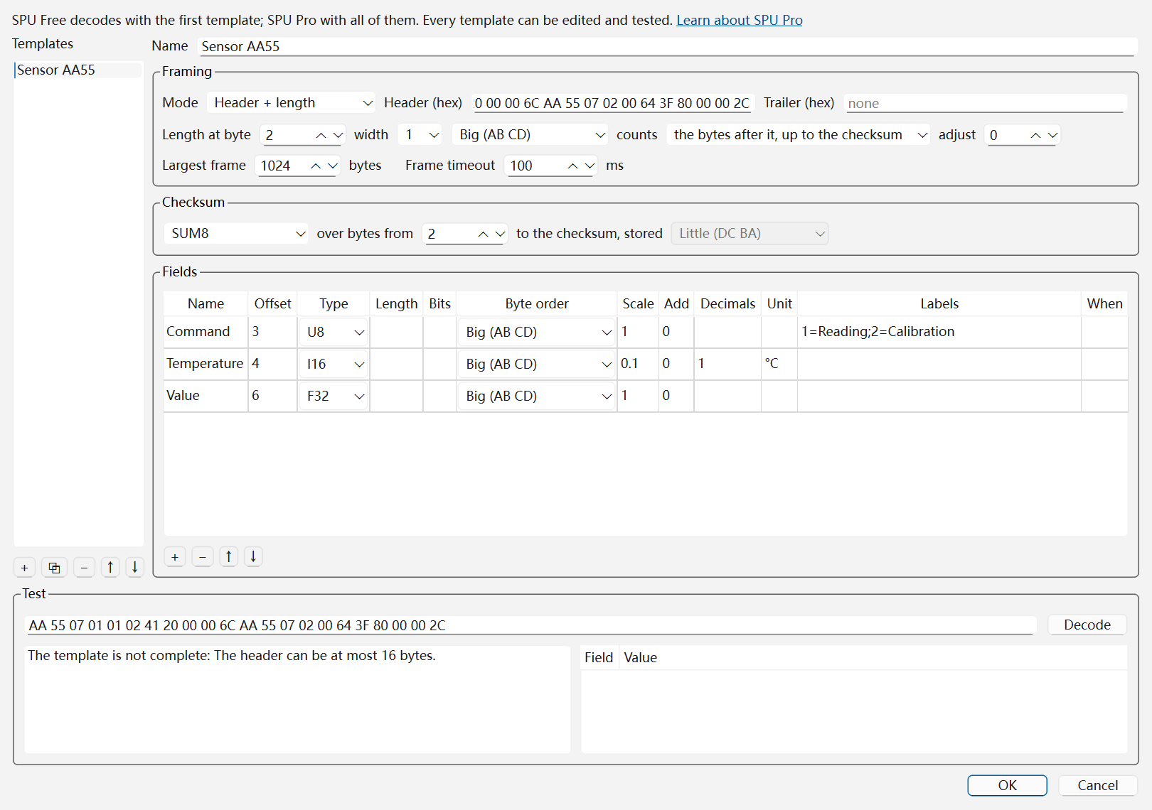
Worked example: a sensor protocol
Say a sensor's manual describes its frames like this:
| Bytes | Content |
|---|---|
| 0–1 | Header AA 55 |
| 2 | Length: the bytes after it, up to the checksum |
| 3 | Command: 1 = reading, 2 = calibration |
| 4–5 | Temperature, signed, big-endian, in 0.1 °C |
| 6–9 | Value, a big-endian 32-bit float |
| 10 | SUM8 of bytes 2 to 9 |
and one of its frames is AA 55 07 01 01 02 41 20 00 00 6C. In Tools → Frame Templates..., add a template and fill it in:
- Name
Sensor AA55; Mode Header + length; Header (hex)AA 55; leave the trailer empty. - Length at byte
2, width1, counts the bytes after it, up to the checksum, adjust0. - Checksum SUM8, over bytes from
2. - Fields:
Commandat offset 3, U8, labels1=Reading;2=Calibration;Temperatureat offset 4, I16, Big (AB CD), scale0.1, decimals1, unit°C;Valueat offset 6, F32, Big (AB CD). - Paste
AA 55 07 01 01 02 41 20 00 00 6C AA 55 07 02 00 64 3F 80 00 00 2Cinto the Test box and click Decode.
Two frames come out, both OK:
Command=Reading (1), Temperature=25.8 °C, Value=10Command=Calibration (2), Temperature=10.0 °C, Value=1
The length byte 07 counts the seven bytes from 01 to 00. The checksum is 07 + 01 + 01 + 02 + 41 + 20 + 00 + 00 = 0x16C, whose low byte is 6C, and the Checksum field reads 0x6C OK. If it reads "(expected …)" instead, the most likely cause is where the sum starts: a SUM8 from byte 0 would include the header and come to 6B. Click OK, choose Sensor AA55 as the connection's decoder, and the sensor's frames are decoded as they arrive.
Exporting and copying
- Copy Selected Rows (Ctrl+C in the table, or in the Export and right-click menus) puts the selected rows on the clipboard as tab-separated text with a header line, ready to paste into a spreadsheet.
- Export → Export Frames (CSV)... writes one row per frame: number, time, direction, peer, protocol, status, length, raw bytes, summary, the paired frame, latency in ms, and all fields in one cell.
- Export → Export Fields (CSV)... writes one row per field, with its value, offset, length and raw bytes, which is what a pivot table wants; a register of a response is named after its group, as in
Registers / 40001.
An export covers the selected rows when more than one is selected, and the whole table otherwise. The files are UTF-8 with a BOM, so Excel opens them with a double click. The column names, the direction (TX / RX) and the status (OK, EXCEPTION, CHECKSUM_ERROR, MALFORMED, INCOMPLETE, UNRECOGNIZED) are fixed English words a script can rely on; summaries and field names follow the language of the app. The default name is the port's name, then -frames- and the date and time.
Free and SPU Pro
In Free, the protocol decode view shows what it does:
- 120 decoding seconds each time SPU starts. A decoding second is a second in which at least one frame was decoded on a live connection; it counts once however many connections and frames it had, and seconds with nothing decoded do not count. The allowance is shared by every connection and every decoder in the window; Unrecognized rows do not count, so a decoder pointed at the wrong protocol does not use it up. Clearing the table does not give seconds back, and a hidden panel decodes nothing and counts nothing. The panel's status line shows the seconds left. When the 120th second is over, decoding pauses until SPU restarts; the receive view carries on as before. Decoding in a replay window is not counted (see Session Replay).
- The first template in the list decodes; the others are marked "(SPU Pro)" in the Decoder list and the editor. Move the one you need to the top with the ↑ button. Every template can still be edited and tested in the Test box.
- Copy Selected Rows is free; CSV export needs SPU Pro.
SPU Pro has none of these limits.